Datasheets Oscillator instellingen
Oscillator mode instellingen maken deel uit van de “config (fuses) settings”. Dit zijn voor instellingen die bepalend zijn hoe de controller opstart (ook na een reset) een soort primaire instellingen dus. Meestal geef je ze in het begin van je programma op. Een Proton voorbeeld voor de 18F25K20 zie je hieronder.
1 2 3 4 5 6 7 8 9 10 11 12 13 14 15 16 17 18 19 20 | CONFIG_START 'primaire oscillator instellingen 'FOSC = HS ;external oscillator FOSC = INTIO67 ;Internal oscillator block, port function on RA6 and RA7 'bijkomende oscillator instellingen FCMEN = Off ;Fail-Safe Clock Monitor disabled IESO = Off ;internal external switchover mode PWRT = On ;power-up timer 'overige instellingen BOREN = On ;brown-out reset BORV = 27 ;brown-out reset value (2,7V) WDTEN = Off ;watchdog timer WDTPS = 128 ;1:128 WDT prescalar PBADEN = Off ;analog port B<4:0> STVREN = On ;;stack overflow reset LVP = Off ;low voltage programming XINST = Off ;Instruction set extension and Indexed Addressing mode disabled (Legacy mode) Debug = Off ;no debug CCP2MX = PORTBE ;CCP2 input/output is multiplexed with RB3 CONFIG_END |
De benamingen kunnen per type PIC verschillend zijn. Zie hieronder de 18F452, 18F25K22 en 18F2550.
1 2 3 4 5 6 7 8 9 10 11 12 13 14 15 16 17 18 19 20 21 22 23 24 25 26 27 28 29 30 31 32 33 34 35 36 37 38 39 40 41 42 43 44 45 46 | CONFIG_START 'Code Protection bits: 18F452 'CP = On ;All of program memory code protected CP = OFF ;Program memory code protection off 'Oscillator Selection bits: 'OSC = LP ;LP oscillator 'OSC = XT ;XT oscillator OSC = HS ;HS oscillator 'OSC = RC ;RC oscillator 'OSC = EC ;EC oscillator w/OSC2 configured As divide-by-4 clock Output 'OSC = ECIO ;EC oscillator w/OSC2 configured As RA6 'OSC = HSPLL ;HS oscillator with PLL enabled/Clock frequency = (4 x FOSC) 'OSC = RCIO ;RC oscillator w/OSC2 configured As RA6 'Oscillator SYSTEM Clock Switch Enable Bit: 'OSCS = On ;Oscillator SYSTEM clock switch option is enabled (oscillator switching is enabled) OSCS = OFF ;Oscillator SYSTEM clock switch option is disabled (main oscillator is source) 'Power-up Timer Enable Bit: PWRT = On ;PWRT enabled 'PWRT = OFF ;PWRT disabled 'Brown-out Reset Enable Bit: 'BOR = OFF ;Brown-out Reset disabled BOR = On ;Brown-out Reset enabled 'Brown-out Reset Voltage bits: 'BORV = 45 ;VBOR Set To 4.5V 'BORV = 42 ;VBOR Set To 4.2V BORV = 27 ;VBOR Set To 2.7V 'BORV = 25 ;VBOR Set To 2.5V 'WATCHDOG Timer Enable Bit: WDT = OFF ;WDT disabled (control is placed On the SWDTEN Bit) 'WDT = On ;WDT enabled 'WATCHDOG Timer Postscale Select bits: 'WDTPS = 1 ;1:1 'WDTPS = 2 ;1:2 'WDTPS = 4 ;1:4 'WDTPS = 8 ;1:8 'WDTPS = 16 ;1:16 'WDTPS = 32 ;1:32 'WDTPS = 64 ;1:64 WDTPS = 128 ;1:128 'CCP2 Mux Bit: CCP2MX = OFF ;CCP2 Input/Output is multiplexed with RB3 'CCP2MX = On ;CCP2 Input/Output is multiplexed with RC1 'Stack Full/Underflow Reset Enable Bit: STVR = OFF ;Stack Full/Underflow will Not cause RESET 'STVR = On ;Stack Full/Underflow will cause RESET CONFIG_END |
.
1 2 3 4 5 6 7 8 9 10 11 12 13 14 15 16 17 18 19 20 21 22 23 24 | ; Oscillator Selection bits: ; FOSC = LP LP oscillator ; FOSC = XT XT oscillator ; FOSC = HS HS oscillator ; FOSC = RC External RC oscillator, CLKOUT function on RA6 ; FOSC = EC EC oscillator, CLKOUT function on RA6 ; FOSC = ECIO6 EC oscillator, port function on RA6 ; FOSC = HSPLL HS oscillator, PLL enabled (Clock Frequency = 4 x FOSC1) ; FOSC = RCIO6 External RC oscillator, port function on RA6 ; FOSC = INTIO67 Internal oscillator block, port function on RA6 and RA7 ; FOSC = INTIO7 Internal oscillator block, CLKOUT function on RA6, port function on RA7 ;Bijkomende Oscillator bits ; Fail-Safe Clock Monitor Enable bit: ; FCMEN = OFF Fail-Safe Clock Monitor disabled ; FCMEN = ON Fail-Safe Clock Monitor enabled ; ; Internal/External Oscillator Switchover bit: ; IESO = OFF Oscillator Switchover mode disabled ; IESO = ON Oscillator Switchover mode enabled ; ; Power-up Timer Enable bit: ; PWRT = ON PWRT enabled (66ms delay) ; PWRT = OFF PWRT disabled ; |
1 2 3 4 5 6 7 8 9 10 11 12 13 14 15 16 17 18 19 20 21 22 23 24 25 26 27 28 29 30 31 32 33 34 35 36 | ; Oscillator Selection bits: ; FOSC = LP LP oscillator ; FOSC = XT XT oscillator ; FOSC = HSHP HS oscillator (high power > 16 MHz) ; FOSC = HSMP HS oscillator (medium power 4-16 MHz) ; FOSC = ECHP EC oscillator, CLKOUT function on OSC2 (high power, >16 MHz) ; FOSC = ECHPIO6 EC oscillator (high power, >16 MHz) ; FOSC = RC External RC oscillator, CLKOUT function on OSC2 ; FOSC = RCIO6 External RC oscillator ; FOSC = INTIO67 Internal oscillator block ; FOSC = INTIO7 Internal oscillator block, CLKOUT function on OSC2 ; FOSC = ECMP EC oscillator, CLKOUT function on OSC2 (medium power, 500 kHz-16 MHz) ; FOSC = ECMPIO6 EC oscillator (medium power, 500 kHz-16 MHz) ; FOSC = ECLP EC oscillator, CLKOUT function on OSC2 (low power, <500 kHz) ; FOSC = ECLPIO6 EC oscillator (low power, <500 kHz) ; ;Bijkomende Oscillator setting bits ; 4X PLL Enable: ; PLLCFG = OFF Oscillator used directly ; PLLCFG = ON Oscillator multiplied by 4 ; ; Primary clock enable bit: ; PRICLKEN = OFF Primary clock can be disabled by software ; PRICLKEN = ON Primary clock enabled ; ; Fail-Safe Clock Monitor Enable bit: ; FCMEN = OFF Fail-Safe Clock Monitor disabled ; FCMEN = ON Fail-Safe Clock Monitor enabled ; ; Internal/External Oscillator Switchover bit: ; IESO = OFF Oscillator Switchover mode disabled ; IESO = ON Oscillator Switchover mode enabled ; ; Power-up Timer Enable bit: ; PWRTEN = ON Power up timer enabled (66ms delay) ; PWRTEN = OFF Power up timer disabled |
1 2 3 4 5 6 7 8 9 10 11 12 13 14 15 16 17 18 19 20 21 22 23 24 25 26 27 28 29 30 31 32 33 34 35 36 37 38 39 40 41 42 43 44 45 46 | ; Oscillator Selection bits: ; FOSC = XT_XT XT oscillator (XT) ; FOSC = XTPLL_XT XT oscillator, PLL enabled (XTPLL) ; FOSC = ECIO_EC EC oscillator, port function on RA6 (ECIO) ; FOSC = EC_EC EC oscillator, CLKO function on RA6 (EC) ; FOSC = ECPLLIO_EC EC oscillator, PLL enabled, port function on RA6 (ECPIO) ; FOSC = ECPLL_EC EC oscillator, PLL enabled, CLKO function on RA6 (ECPLL) ; FOSC = INTOSCIO_EC Internal oscillator, port function on RA6, EC used by USB (INTIO) ; FOSC = INTOSC_EC Internal oscillator, CLKO function on RA6, EC used by USB (INTCKO) ; FOSC = INTOSC_XT Internal oscillator, XT used by USB (INTXT) ; FOSC = INTOSC_HS Internal oscillator, HS oscillator used by USB (INTHS) ; FOSC = HS HS oscillator (HS) ; FOSC = HSPLL_HS HS oscillator, PLL enabled (HSPLL) ; ;Bijkomende Oscillator setting bits ; PLL Prescaler Selection bits: ; PLLDIV = 1 No prescale (4 MHz oscillator input drives PLL directly) ; PLLDIV = 2 Divide by 2 (8 MHz oscillator input) ; PLLDIV = 3 Divide by 3 (12 MHz oscillator input) ; PLLDIV = 4 Divide by 4 (16 MHz oscillator input) ; PLLDIV = 5 Divide by 5 (20 MHz oscillator input) ; PLLDIV = 6 Divide by 6 (24 MHz oscillator input) ; PLLDIV = 10 Divide by 10 (40 MHz oscillator input) ; PLLDIV = 12 Divide by 12 (48 MHz oscillator input) ; ; System Clock Postscaler Selection bits: ; CPUDIV = OSC1_PLL2 [Primary Oscillator Src: /1][96 MHz PLL Src: /2] ; CPUDIV = OSC2_PLL3 [Primary Oscillator Src: /2][96 MHz PLL Src: /3] ; CPUDIV = OSC3_PLL4 [Primary Oscillator Src: /3][96 MHz PLL Src: /4] ; CPUDIV = OSC4_PLL6 [Primary Oscillator Src: /4][96 MHz PLL Src: /6] ; ; USB Clock Selection bit (used in Full-Speed USB mode only; UCFG:FSEN = 1): ; USBDIV = 1 USB clock source comes directly from the primary oscillator block with no postscale ; USBDIV = 2 USB clock source comes from the 96 MHz PLL divided by 2 ; ; Fail-Safe Clock Monitor Enable bit: ; FCMEN = OFF Fail-Safe Clock Monitor disabled ; FCMEN = ON Fail-Safe Clock Monitor enabled ; ; Internal/External Oscillator Switchover bit: ; IESO = OFF Oscillator Switchover mode disabled ; IESO = ON Oscillator Switchover mode enabled ; ; Power-up Timer Enable bit: ; PWRT = ON PWRT enabled ; PWRT = OFF PWRT disabled |
De selection bits voor andere type PIC’s kun je terug vinden onderin de device.inc files zoals die in de “C:\Program Files\Microchip\MPASM Suite” directory staan als je Microchip MPLAB daar geinstalleerd hebt. (Download)
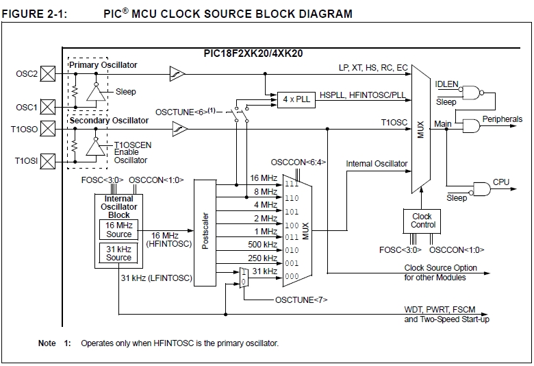
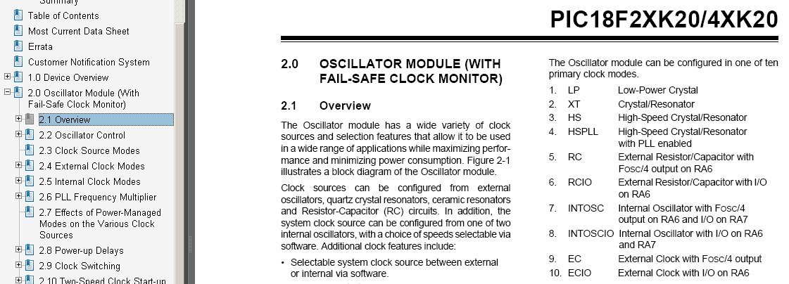
Hierboven het blok schema van het 18F25K20 oscillator deel.
Bij de verschillende blokken worden diverse register namen genoemd (FOSC, OSCTUNE, OSCCON) deze registers bepalen hoe het oscillator deel ingesteld wordt. het FOSC register zijn de eerder genoemde oscillator selectie bits config (fuse) instellingen. Deze bepalen dus of de oscillator in LP, XT, HS, RC, EC of Internal mode opstart.(later meer over deze modes)
Indien in internal mode (interne oscillator van de 18F25K20, geen kristal dus) wordt opgestart, komt het OSCCON register om de hoek kijken. Hoofdstuk 2.2. De interne oscillator werkt op 16Mhz en kan op 8 manieren gedeeld worden, OSCCON bit 6 tot 4 bepalen de deel factor. Andere instellingen van het OSCCON register vallen buiten deze uitleg.
Hoofdstuk 2.3 en 2.4 gaan over de Clock modes. We beperken ons tot de 3 kristal oscillator modes, LP, XT en HS. LP is voor b.v. horloge kristallen (31Khz). XT is voor kristallen tot 4 Mhz. HS is voor hogere frequenties.
Hoofdstuk 2.5 behandelt de al eerder genoemde Internal Clock Mode. buiten het OSCCON register hebben we hier ook nog het OSCTUNE register met als belangrijkste instelling het in en uit schakelen van het PLL blok met bit 6 (PLLEN). PLL vermenigvuldigd de oscillator frequentie met 4x. Voor de interne oscillator werkt dit alleen als 16 of 8Mhz geselecteerd is. De PLL kan hier dus niet met een primaire (fuse) setting geactiveerd worden. Een andere instelling die met het OSCTUNE register te maken is, is fijn tuning van de interne oscillator met bit 5 tot 0 van het register.
Hoofdstuk 2.6 behandelt de HSPLL setting (HS oscillator mode met 4x de kristal frequentie) en de hierboven beschreven interne oscillator met PLL.
De rest van Hoofdstuk 2 valt buiten het bestek van deze uitleg.
Bijkomende oscillator settingen komen hier aan bod. De belangrijkste is de fuse setting PWRT (delay om het kristal 66ms opstart tijd te geven voor een stabiele frequentie) die voor simpel gebruik altijd op ON gezet wordt.
De FCMEM en IESO fuse settingen kunnen voor simpel gebruik op OFF gezet worden.